
This guide will walk you through the process of upgrading your ArduPilot Mega autopilot with a Telemetry Kit, enabling two way communications between your Ground Control Station and UAV. Giving you the ability to change missions, or evin change configuration parameters while your UAV is circling above you. This kit is available from the Unmanned Tech Shop
Soldering the Xbee adaptor modules
IF you did not buy the pre configured and soldered kit, you will need to build the Xbee modules yourself. This is fairly easy, only requiring you to solder some headers onto the module.
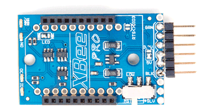
Start with soldering the right angle header onto your XtreamBee FTDI module as shown in the images below. It is important to solder a connection between the 5V+ and CTS pins (click on the images below for a better view), this is required for the 2.4Ghz modules. Once this is done solder on the female headers, it is important not to use too much solder for the female headers as the solder will fill the holes and make it difficult to plug in the Xbee modules.
Start with soldering the right angle header onto your XtreamBee FTDI module as shown in the images below. It is important to solder a connection between the 5V+ and CTS pins (click on the images below for a better view), this is required for the 2.4Ghz modules. Once this is done solder on the female headers, it is important not to use too much solder for the female headers as the solder will fill the holes and make it difficult to plug in the Xbee modules.
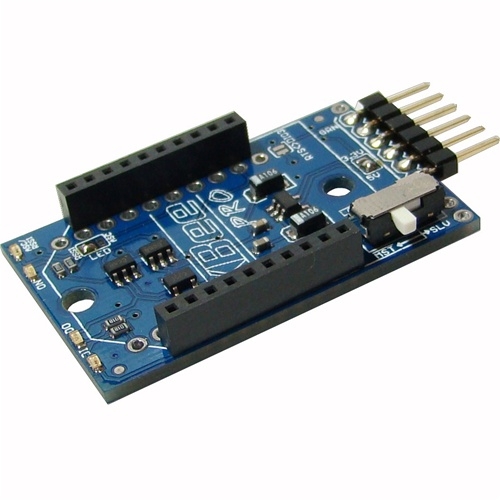
No you just need to solder the female headers for onto the XtreamBee USB module, once again make sure that you do not use too much solder.

Soldering the connectors on IMU

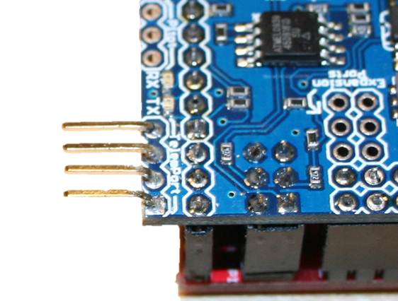
ArduPilot Mega with telemetry port headers, click image for full size
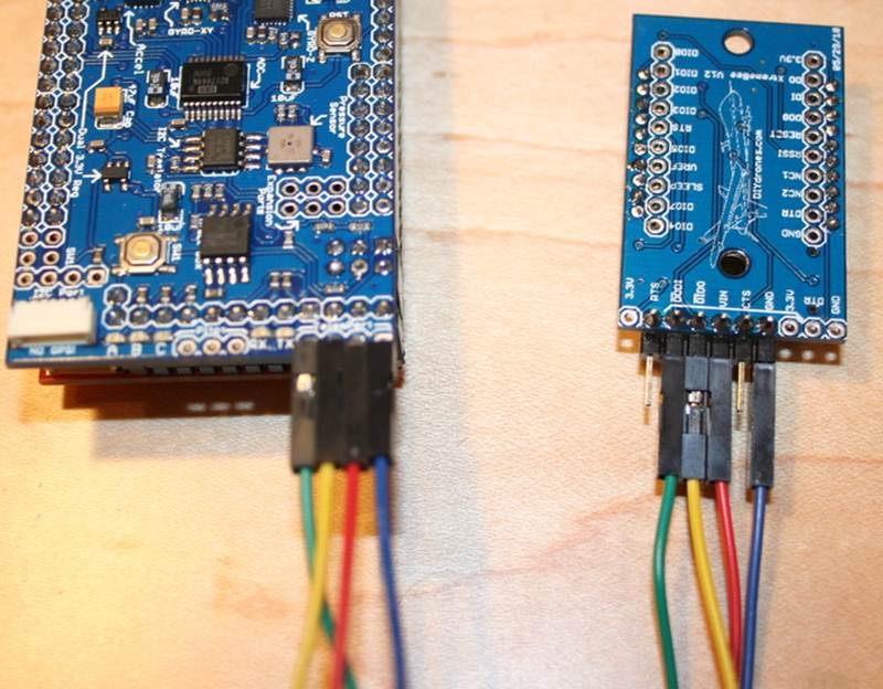
The next step is to solder some headers onto your ArduPilot Mega IMU shield. You will need to add four male header pins onto the 'TelemPort' as shown in the image. If you want you can also mount the pins upside-down if you have a space problem, or you could use right angle headers, or bend the straight angle headers as shown below.

Wiring it all together
This step assumes that you have already soldered your Xtremebee modules. If you have not done so, please read the guide on building Xtremebee modules.
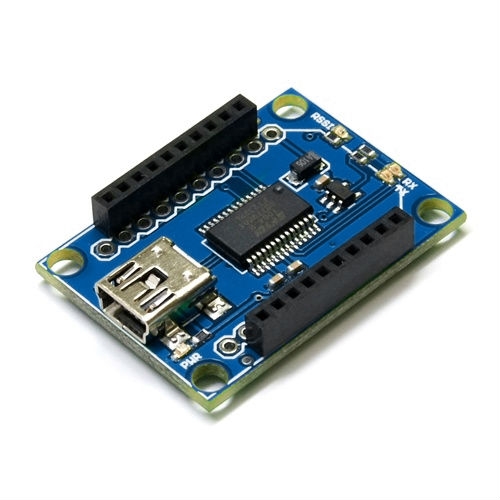
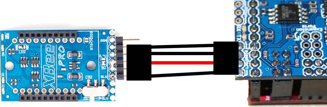
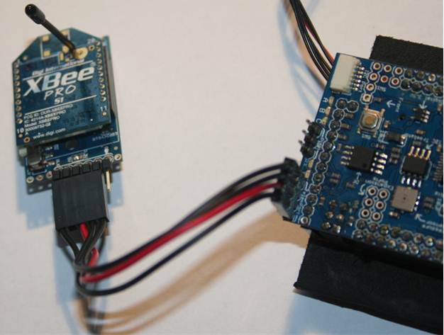
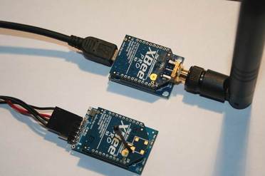
Using the cable provided in the Xbee Telemetry Kit you can attach you Xtremebee module to Ardupilot Mega. The images below show how to connect the two together. As an alternative you can also use jumper wires if you want. Click on the images to view the large version
Using the cable provided in the Xbee Telemetry Kit you can attach you Xtremebee module to Ardupilot Mega. The images below show how to connect the two together. As an alternative you can also use jumper wires if you want. Click on the images to view the large version
Configuring Modules
If you purchased the pre configured kit from Unmanned Tech, then you can skip this step.
Once the modules have been build, you will need to configure them using X-Ctu which is a free program that runs on windows. Download and install the latest version of X-Ctu here.
Once the modules have been build, you will need to configure them using X-Ctu which is a free program that runs on windows. Download and install the latest version of X-Ctu here.
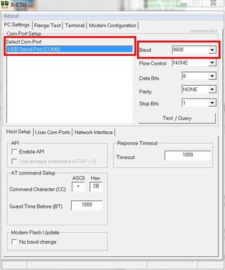
In order to configure each Xbee modem you will need to connect it with the XtremeBee USB board. Once X-Ctu has been installed you will first need to go the the PC settings tab. You must select the relevant comm port and choose a boad rate of 9600. By default Xbee modules come with the baud rate set at 9600, and we will need to change this to 57600 to use with ArduPilot Mega. To verify that you can connect press the Test/Query button and you should get a success window, if not make sure you have chosen the correct com port, or baud rate.
Once you have configured the baud rate (next step) you will need to choose the baud rate of 57600 to configure your module in the future.
Once you have configured the baud rate (next step) you will need to choose the baud rate of 57600 to configure your module in the future.
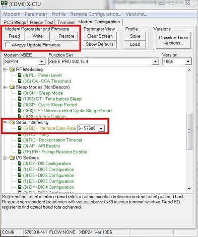
Now go the the Modem Configuration Tab, and click the read button, all of the settings for the modem should load. Scroll down to the serial interfacing section, and change the Baud Rate to 57600.
Now click on the Write button for the settings to be written to your modem. You will need to configure each modem this way.
If you want you can also change the PAN ID to something different, this will need to be the same for each Xbee module that you are using in the network, its recommended that you leave this as default unless you will by flying around other xbee networks.
If you need to change settings at a later stage, make sure you choose the baud rate of 57600 on the PC settings tab as the modems work on 57600 baud now.
Final Steps
Attach your xbee pro module with the whip antenna to the XtremeBee FTDI board, this will go on your aircraft. The xbee pro module with the RPSMA antenna attached to the XtremeBee USB board which will be used to connect with your Ground Station PC.
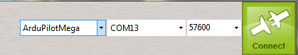
Now open up your favourite ground control station, such as the ArduPilot Mega Mission Planner, and select the com port of your xbee module, and choose the baud rate and connect!
Now open up your favourite ground control station, such as the ArduPilot Mega Mission Planner, and select the com port of your xbee module, and choose the baud rate and connect!
 RSS Feed
